Map every wetted surface
List housing, diaphragm, seal compound, cable jacket and feedthrough. PTFE housing does not qualify ceramic, adhesives or O-rings. Identify diluted product, concentrate, contamination and cleaning exposure separately.
APPLICATION ENGINEERING / SLV-PTFE
A tank can contain a compatible bulk chemical and an incompatible cleaning solution. Put both on the material schedule before choosing the probe.
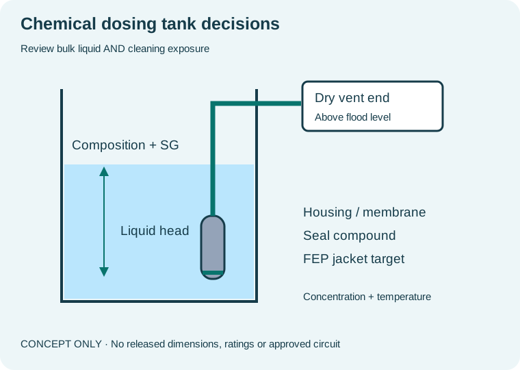
RESOLVE THESE DECISIONS BEFORE ORDERING
List housing, diaphragm, seal compound, cable jacket and feedthrough. PTFE housing does not qualify ceramic, adhesives or O-rings. Identify diluted product, concentrate, contamination and cleaning exposure separately.
Concentration and temperature change density. The same pressure can indicate different heights after a batch change. Agree the density basis for the sensor and PLC, and whether the operator needs height, volume or mass.
Terminate above flood level in an appropriate protected location. Review corrosive vapour at the breather and enclosure. A sealed gland around the cable must not seal the atmospheric reference path.
WORKED EXAMPLE — ASSUMPTIONS, NOT A CUSTOMER CASE
Assume SG 1.42 at operating temperature and maximum liquid column 3 m above the diaphragm.
P = 1.42 × 9.80665 × 3 = 41.7763 kPa. This is calculated pressure at the stated density, not a recommended stock range.
A 6 m FEP cable request could cover a 3.5 m installed path + 1.5 m surface route + 1 m service allowance. Confirm the actual path, bend radius and immersion conditions. The example density does not approve any chemical concentration.
Recalculate using your liquid density and head →PROJECT ACCEPTANCE CHECKLIST
Concentrated mixtures, HF-containing liquids, unknown cleaning chemistry and high-temperature chemicals need specific evidence. Keep unresolved combinations in engineering review rather than assuming the PTFE family fits.
Review SLV-PTFE configuration & selection brief →Attach your installed nameplate, tank or well drawing, and input specification to the RFQ. Unresolved values can be stated as unknown for engineering review.
Only after the complete assembly is reviewed for each chemical, concentration, temperature and exposure. Housing compatibility is insufficient.
Use the tank geometry, diaphragm offset and agreed volume table. Density affects pressure-to-height scaling; irregular geometry affects height-to-volume scaling.
START WITH YOUR INSTALLATION
Specify chemical submersible probes from concentration, temperature, complete wetted materials and actual liquid density.
Define low-head diesel tank measurement with fuel blend, usable level, cable route, area classification and generator input.
Plan groundwater pressure span, deployment cable, surveyed datum and low-power logger integration for borehole networks.
Select a wastewater hydrostatic probe around rags, grease, turbulence, cleaning access, vent protection and pump-control acceptance.